Installation Instructions – DriveDrain
Every project is unique and some require more detailed instructions and possibly changes to the information provided on this website. Below you’ll find ‘standard’ installations for reference.
Installers must observe the relevant codes of practice and standards legislated. We recommend contractors contact ‘Dial Before You Dig’ on 1100 or at www.1100.com.au. Site conditions may require additional reinforcement or a change to these details that may need to be provided by an engineer.
Typical installation for Class A to Class C
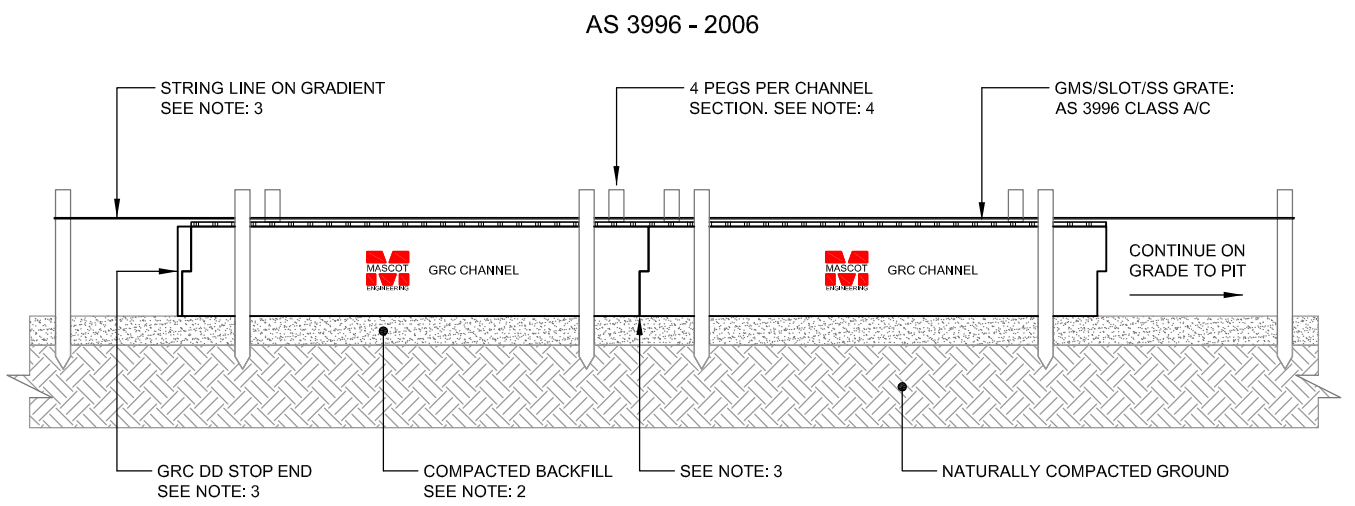
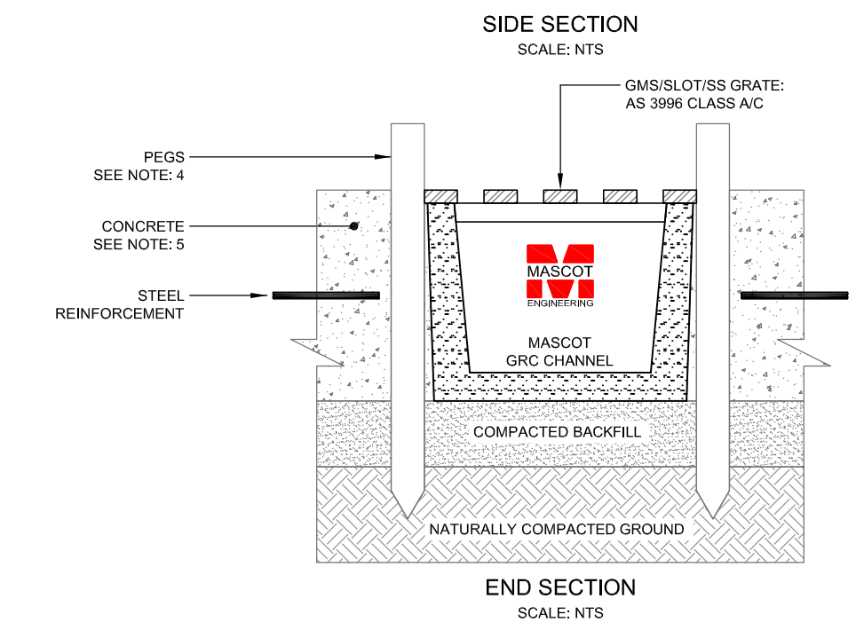
Installation Instructions for Class A to Class C
- Excavate soil according to concrete floor levels and allow for depth of GRC Drive Drain/Speed Drain Channel. Specifications are available in the Channel Systems brochure. It is recommended that whilst determining levels, ensure grate is fitted in channel.
- Prior to sitting and positioning channel, ensure that the backfill for the bedding for the channel is compacted, levelled and on grade.
- Position GRC channel with grate fitted, use a string line to maintain concrete slab level to channel. Use a spirit level to check for fall and ensure channel maintains a continuous gradient to its outlet. To prevent ground water ingress/egress at all joints, use Mascot’s two part epoxy between channel joints and to hold stop ends in place. Mascot epoxy available at Mascot Engineering 1300 885 295. Prior to concrete pour, apply PVC/Cloth backed Duct Tape to top of grating to prevent concrete entry into channel and damage to the grating.
- With all channels in position, use four (4) pegs per channel to lock into position to prevent any movement during concrete pour.
- If using a concrete pump, avoid resting pump line on the channel and do not pump concrete directly onto channel as excess force may twist the channel. NOTE: Do not remove grate during pour, as the sides of the channel may be pushed in due to lateral concrete pressure.
- Once concrete is poured on either side of channel, push concrete against channel on both sides with a steel trowel and slowly remove pegs.
- Finish concrete level to top of grate. Once concrete has set, remove duct tape and clean any concrete residues from the channel and grating.
Typical installation for Class D
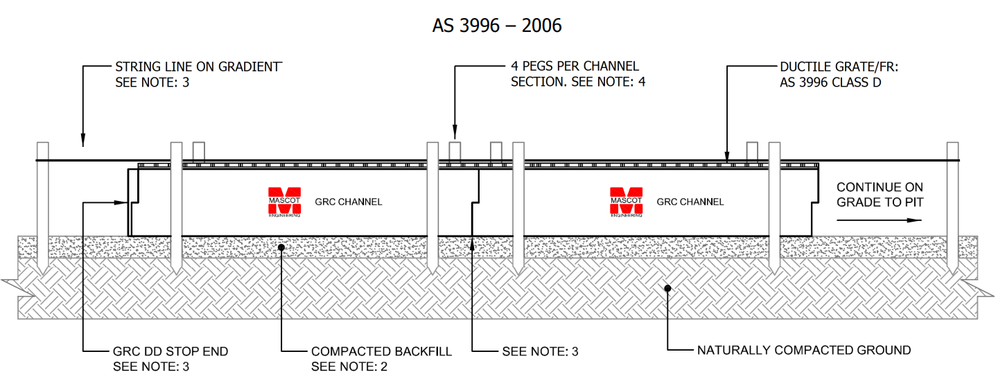
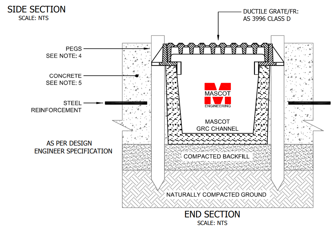
Installation Instructions for Class D
- Excavate soil according to concrete floor levels and allow for depth of GRC Drive Drain. Specifications are available in the Channel Systems brochure. It is recommended that whilst determining levels, ensure grate is fitted in channel.
- Prior to sitting and positioning channel, ensure that the backfill for the bedding for the channel is compacted, levelled and on grade.
- Position GRC channel with grate fitted, use a string line to maintain concrete slab level to channel. Use a spirit level to check for fall and ensure channel maintains a continuous gradient to its outlet. To prevent ground water ingress/egress at all joints, use Mascot’s two part epoxy between channel joints and to hold stop ends in place. Mascot epoxy available at Mascot Engineering 1300 885 295. Prior to concrete pour, apply PVC/Cloth backed Duct Tape to top of grating to prevent concrete entry into channel and damage to the grating.
- With all channels in position, use four (4) pegs per channel to lock into position to prevent any movement during concrete pour.
- If using a concrete pump, avoid resting pump line on the channel and do not pump concrete directly onto channel as excess force may twist the channel. NOTE: Do not remove grate during pour, as the sides of the channel may be pushed in due to lateral concrete pressure.
- Once concrete is poured on either side of channel, push concrete against channel on both sides with a steel trowel and slowly remove pegs.
- Finish concrete level to top of grate. Once concrete has set, remove duct tape and clean any concrete residues from the channel and grating.