Installation Instructions – Technodrain
Every project is unique and some require more detailed instructions and possibly changes to the information provided on this website. Below you’ll find ‘standard’ installations for reference.
Installers must observe the relevant codes of practice and standards legislated. We recommend contractors contact ‘Dial Before You Dig’ on 1100 or at www.1100.com.au. Site conditions may require additional reinforcement or a change to these details that may need to be provided by an engineer.
Choosing the right product for your project.
The first step is understanding which grating and channel are appropriate for your project. Before commencing works ensure that the correct products have been chosen in terms of channel clear opening and depth, class load rating, design elements specified in the architectural and technical project (e.g. heelproof, grating materials) and surface drainage requirements in relation to hydraulic sizing.
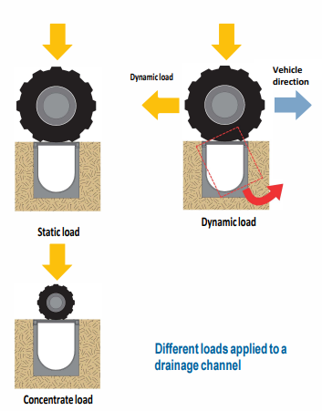
When assessing the appropriate load class for your product it is important to consider all possible traffic as well as the environment of the installation. Whilst nominal wheel loads are good for reference, reviewing the operating environment (e.g. vehicles travelling at highspeed or ones that turn and brake on the gratings will apply a dynamic load much greater than a simple static load) and possible future uses is key.
An area that is occasionally subjected to, or in specific cases, heavy and dynamic loads (e.g passing of garbage trucks or emergency vehicles, goods unloading, forklift trucks) has to be installed with the appropriate channels and gratings for the most sustainable demanding use, e.g. the solid tyre of a forklift applies a high concentrated wheel load relative to other vehicles of the same weight.
The diagrams below show static, dynamic and concentrated loads as examples.
Hydraulic Sizing of the drainage system
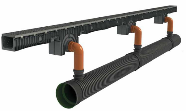
The water collection and discharge system (channel + outflow pipes) should be sized according to:
– The pluviometric and meteorological characteristics of the site;
– The form and sloping of the collection area;
– The type of paving used (asphalt, concrete, paving stones, etc);
– And possible aggressive characteristics of the liquid being collected in the channels.
Attention must be paid to adjacent construction such as access roads that can pour water directly into the drainage area. In this case, the area considered for drainage must be the sum of all these components (open-area, possible access routes, coverings). It will also be necessary to consider recent climate change that entails frequency of rain of short duration but high intensity, capable of saturating the existing drainage networks in a short time.
For this reason, an appropriate security coefficient will have to be considered, to be applied to the maximum drainage capacity of the system chosen.
Installation
Technodrain channel and grate system requires a base of concrete appropriate to spread the weight load in accordance with the Class rating of the product selected.
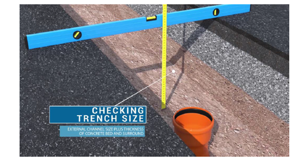
Preparing for Installation
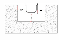
- The excavation/trench for the installation of the Technodrain drainage system must take into account the overall width and depth of the channel selected and the thickness of concrete required in table 1 below.
- In addition to these dimensions (Channel plus W and D from Table 1) the excavation should allow for the possible passage/inclusion of pipes to the final drain connection if required.
- The natural ground the channel is being laid in must have a bearing capacity sufficient to support the load class of the product being installed. It may be necessary to increase the bearing capacity by tamping down the foundation or providing some form of ground or soil reinforcement.
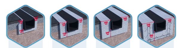
Table 1 – Recommended dimensions (in addition to the chosen channel) for foundation and concrete support.
| Load Ratings as per AS3996 | Class A | Class B | Class C | Class D | Class E | Class F | Class G |
|---|---|---|---|---|---|---|---|
| D - Depth Under Channel | 100mm | 100mm | 150mm | 150mm | 200mm | 250mm | 250mm |
| W - Width to Side of Channel | 100mm | 100mm | 150mm | 150mm | 200mm | 250mm | 250mm |
*All dimensions are in mm. Typical installation guide only and does not take into account any site specific limitations or requirements.
Concrete Foundation
- The trench/excavation must be prepared to provide for a concrete base thickness of D (table 1).
- The concrete to be used for the base of the Technodrain channel must have properties conducive to fill all cavities formed by the ribs external reinforcement channel. For the same reason the size of aggregates in the concrete content should not exceed 15mm-18mm diameter.
- The minimum strength class of concrete of the foundation and abutment must be between 25 to 30 MPa for grate load classes up to Class D and 38 to 40 MPa for products from Class E to Class G.
- There are many premixed mortars in the market that may be used to reduce curing time and possible shrinkage.
Technodrain Channel Placement
- Begin the installation from the point of discharge (sump), connecting the outlet to the stormwater system. For a perfect seal of the Technodrain tongue and groove connection point, use a thixotropic bituminous type sealant or suitable adhesive sealant.
- Each channel should be installed with the grates already secured in place, it is therefore recommended to check and tighten fixings prior to placing the Technodrain in the excavation. Care should be taken in ensuring the correct placement and orientation of grates on the channel before tightening the fixing screws. If grates are not in position correctly, it is possible that installation may cause deformities to the channel.
- To connect stormwater pipes to the Technodrain channel, use an appropriate sized holesaw and drill out the required size hole in the bottom, side or end cap located on the Technodrain Channel. Ensure the internal edges are clean and free of debris prior to connecting/sealing the stormwater pipe with a suitable adhesive.
Completion
- Ensure the edge of the channel is not distorted during concreting to prevent issues with water draining correctly and grate removal. An expansion/compression joint/strip can be used also depending on the finished surface and expected loads.
- It is important that the finished surface around the channel remains 3-5mm above the surface of the grating.
- It is recommended to protect the grating and channel from residual concrete during installation.
- For Class E and above installations, we recommend reinforcing the concrete with steel to increase strength. Please note, some channels are fitted with anchoring points as shown.
- Ensure concrete has cured prior to use.