Installation Instructions – Access Covers
The information set out on these pages is a guide only and does not take into account any site specific limitations or requirements. This information covers our range of Concrete Infill, Solid Top and Paver Infill (gastight) iron covers and frames. For more information on your cover, contact 4you@mascoteng.com.au or 1300 885 295.
Mascot Engineering covers and frames are mated individually during the machining process, therefore they are not always interchangeable. A cover from one frame will not necessarily fit another. Covers in Multi-parts are marked and designated to a particular location in the frame and bespoke installation instructions are provided with your cover.
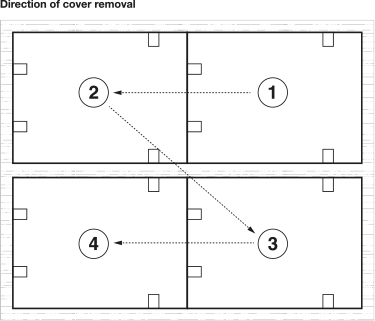
The direction a cover can be removed from its frame is indicated by the cover edge with two keyholes. If there is an obstruction (wall, bollard etc), ensure the cover is positioned in a direction away from the obstruction. See drawing ‘Direction of cover removal’.
All infill covers and frames must be filled with structural grade concrete (refer to AS3996 for further information).
Please handle all products with care. Frames may suffer twisting and damage to joints if mistreated.
Single, Two and Three Part Access Covers and Frame
NOTE: Not to be used for decorative edge or multipart installation. For details, contact 1300 885 295 or
4you@mascoteng.com.au
- Form the access pit and rebate to the size required. See charts for recommended rebate dimensions for your cover.
- Remove all the keyhole plugs and boltdown bolts (if fitted) from the covers and remove the covers from the frame using Mascot Engineering Lifting Keys (Click Here for details).
- For 2 or 3 part covers, mark the frame and covers to ensure they are reinstated in the same position.
- Position the frame in the rebate and ensure the lifting end of the frame is not obstructed (as per ‘direction of cover removal’ drawing). Ensure the covers are placed in a direction suitable for traffic flow. NOTE: The frame must not protrude into the opening, it must be fully supported.
- Pack under the cover of the frame joints until level with the finished floor. For 2 or 3 part covers, pack under the frame joints to prevent sagging.
- Prepare internal formwork ensuring the frame will be fully supported. For covers with ‘holes’ to reduce the overall weight, cover with metal sheeting or similar prior to pouring.
- Clean the seating area of the covers and frame. These surfaces must be dirt and dust free.
- Using the marks on the frame and cover (as per above), place the covers back into the frame ensuring the top edges of the covers are level with the frame. Check the covers for any rocking or movement and adjust packing as required.
- Cover all keyhole plugs and boltdown points.
NOTE: For some loadings, reinforcing may be required in the rebate under the frame. This reinforcement should be installed to the engineer’s details.
Concrete Pour
- Simultaneously fill the rebate gap, frames and infill covers with concrete. If using Paver Infill Covers, there is no need for any concrete to be in the cover recess to achieve the loading.
- Ensure that the concrete is well compacted and the frame is fully supported.
- Screed off excess concrete and finish the surface as required. The edges of the cover and frame should be visible.
- Concrete must be allowed to cure before removing the covers from the frame. Removing covers prior to curing may result in damage.
- Once cured, remove covers with a Mascot Engineering Lifting Key and strip the internal formwork.
- Ensure the seat areas are clean and greased prior to reinstating the covers in the frame.
- Cover and Frame seat areas should be liberally greased periodically to assist in the maintenance of the product. Grease detail can be found here.
- Using a rubber mallet, tap down on the key hole surround until the cover is level with the frame.
- Reinstall all covers/plugs to keyholes and bolt down access.
Maintenance & Access
To ensure easy access when required, Mascot Engineering recommends the following. This process should be followed whenever lifting the cover or at least once annually and is applicable to covers fitted with Australian Standard Lifting Keyholes as specified in AS3996.
- Remove the key hole plugs, bolt hole plugs and bolts (if fitted).
- Using either a Mascot Engineering Short or Long Handle Lifting Key – insert into keyholes (see drawing ‘Direction of Cover Removal’) and rotate 45 degrees to lock into position.
- Position the jacking screw over the frame (ensure you protect any decorative edge and surface finishes). Using a spanner, screw down to break the seal of the cover to the frame. If you experience difficulties breaking the seal, apply penetrating oil and allow 24 hours – and try again.
- Once the seal is broken, lean forward on the lifting keys and lift the cover from the frame. Place a section of pipe under the edge to enable the cover to be rolled clear of the opening.
- For multiple cover units, remove covers in order and store to ensure they are replaced in the same order and position.
- Prior to reinstating the cover, ensure the cover and frame seat is clean and free of all debris and liberally apply grease.
- Using Mascot Engineering lifting keys (you can utilise the other two lifting key holes, roll the covers back into position and gently down into the frame.
- Replace all caps, plugs and bolts.
Click Here to view our range of Lifting Keys.
Multipart Installation
These instructions are a guide only and should be read with the supplied product drawing. The installer should be familiar with single part installation prior to attempting the below.
- Check the rebate dimensions are the pit opening size against the product ordered.
- When unpacking the sections of the frame, take care not to crush, twist or damage the joints.
- Place undercut and drawcut (see traffic flow drawing) frames in the rebates and attached to ‘beam box’ (only applicable if unit is complete with removable beams) or to each other. Use the numbers on the units and the associated drawing as reference. Ensure top of beam box and frames are flush.
- Place side frames in rebates as per supplied drawing and numbers on the unit. Remove nuts and washers from side frames and attach to end frames – use hand tools only.
- Ensure all four corners are to the finished surface level – use stringline if necessary. Use appropriate packers as required (remember the required loading, timber is not suitable).
- Clean the frame’s vertical and horizontal seating sections – as well as the corresponding section on all covers.
- Select a row to start, place the covers into frame – start at drawcut end. Note: the drawcut is identified on the cover with the two keyholes on the same side of the cover.
- Begin placing covers into the row using the numbers on the covers and corresponding drawing supplied. Check covers for any rocking in the frame – if detected, check rebate cleanliness and use packers as required.
- Continue installing each cover into the frame, checking each for rocking. As covers are put in place, the frame will begin to straighten. Check all contact points – this product is designed to be extremely tight with little tolerance to ensure it is gastight.
- The frame may need a packer or wedge to hold tight – this may need to be kept in place during the concrete pour.
- See previous instructions regarding the ‘concrete pour’ to continue.